PCBA quality control and testing are integrated into each stage of MG PCBA’s manufacturing workflow. Inspection and test requirements are reviewed with the customer’s production files before assembly begins, helping the team select appropriate controls for the component package, board complexity and intended application.
Our available quality controls include incoming material verification, solder paste inspection, visual inspection, automated optical inspection, X-ray inspection, programming and functional testing when required. Inspection and production information can also be recorded to support lot identification, process review and project traceability.
Incoming Material and Component Verification
Quality control begins before components and bare PCBs enter production. Incoming materials are checked against the approved BOM and purchasing information, including manufacturer part numbers, package types, quantities and approved alternatives. Labels and packaging information are reviewed to reduce the risk of incorrect or mixed materials entering the assembly process.
Bare PCBs and customer-supplied materials are also checked against the available project documentation before release to production. Storage conditions, moisture-sensitive handling and material preparation are managed according to the component and assembly requirements. Any visible discrepancy or unclear identification is reviewed before manufacturing continues.
Solder Paste and Process Control
For SMT assembly, process control begins with solder paste preparation and printing. The stencil, solder paste type and printing parameters are selected according to the approved PCB design and assembly requirements. Printed boards can be checked for paste coverage, alignment and consistency before component placement begins.
During placement and reflow, equipment settings and process conditions are managed according to the board design, component package and approved production instructions. Process checks help identify printing, placement or soldering concerns before assemblies proceed to later inspection stages.
Visual Inspection and Automated Optical Inspection
Visual inspection is used throughout PCBA production to check component presence, orientation, polarity, solder joints and visible workmanship conditions. Inspectors compare the assembled boards with the approved BOM, assembly drawings and work instructions. Any identified concern is reviewed before the boards move to the next production stage.
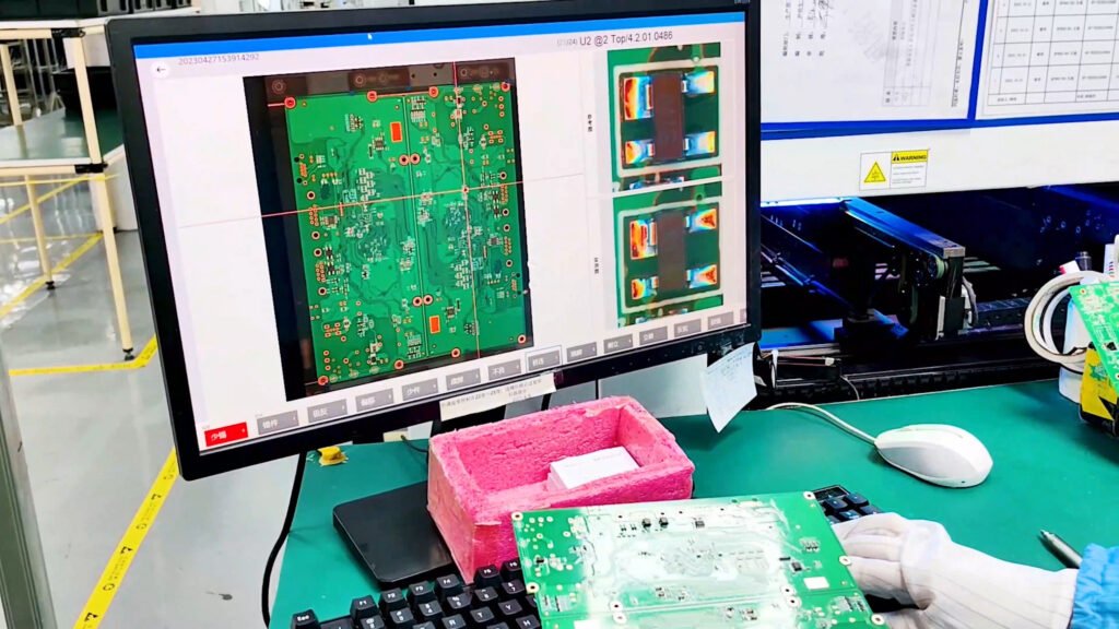
Automated optical inspection, or AOI, provides an additional check after component placement and soldering. AOI equipment can help identify missing or shifted components, polarity errors, solder bridging and other visible assembly conditions. Inspection findings are reviewed by trained personnel because automated results may require confirmation against the approved production documentation.
X-Ray Inspection for Hidden Solder Joints
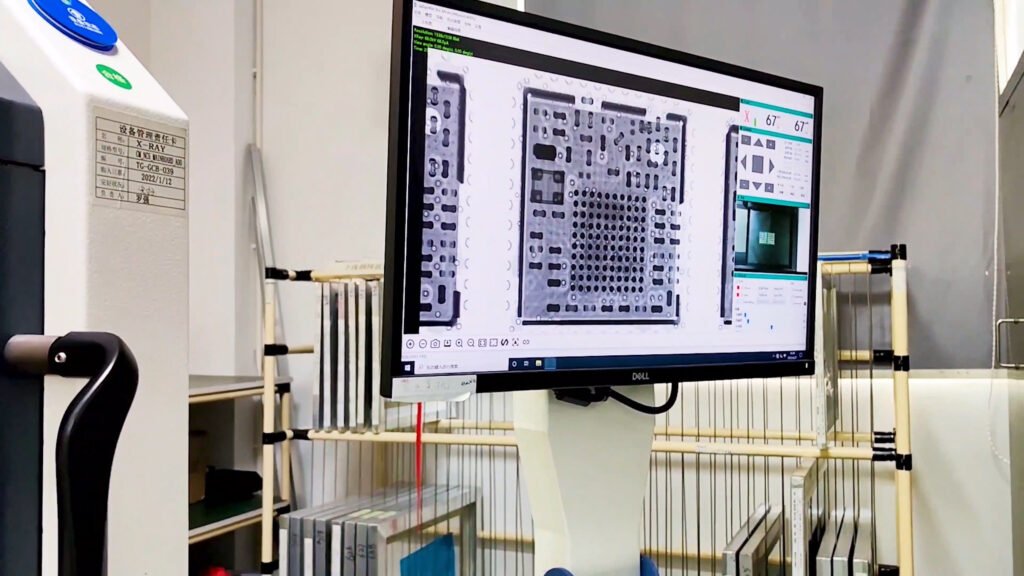
Some solder joints cannot be fully evaluated by visual inspection or AOI because they are located beneath the component package. X-ray inspection may be used for assemblies containing BGAs, QFNs and other components with hidden solder connections. It allows the inspection team to examine solder distribution, alignment and possible internal defects without removing the component.
The need for X-ray inspection is determined by the component type, board complexity and customer requirements. Inspection images and findings can be reviewed as part of the quality evaluation before boards proceed to functional testing or final acceptance.
Programming and Functional Testing
Programming and functional testing can be performed when the customer provides the required firmware, programming method, test procedure and acceptance criteria. Before testing begins, the engineering team reviews the available instructions, required interfaces and any dedicated fixtures needed for the project.
Depending on the assembly, testing may include continuity checks, power-on verification, firmware programming and functional testing. Test results are evaluated against the approved criteria, and identified issues are reviewed before boards proceed to final inspection, packing and delivery.
Traceability and Production Records
Production traceability can be maintained according to the project requirements and available manufacturing records. Material information, assembly stages, inspection findings and test results may be linked to the relevant production lot or work order.
When specific documentation is required, customers should provide the record format, identification method and retention requirements before production begins. Available records can support lot identification, process review, quality follow-up and repeat manufacturing.
Quality Management Systems
MG PCBA’s quality and environmental control framework is supported by documented management systems covering quality, environmental responsibility and hazardous substance process management.
ISO 9001 – Quality Management System
ISO 14001 – Environmental Management System
IECQ-HSPM QC 080000 – Hazardous Substance Process Management
These systems support controlled procedures, production records, inspection activities, corrective actions and continuous process improvement. Project-specific quality and acceptance requirements should be confirmed before production begins.
Discuss Your PCBA Quality Requirements
Quality and testing requirements vary according to the component package, board complexity and intended application. Please provide the required inspection methods, test procedures, firmware, fixtures, acceptance criteria and documentation requirements before production begins.
MG PCBA supports prototype, pilot-run and low- to mid-volume PCBA manufacturing with visual inspection, AOI, X-ray inspection, programming, functional testing and production traceability. Submit your project files through our Request a PCBA Quote page, and our team will review your quality and testing requirements.